

Please sign in so that we can notify you about a reply
OperationUnder normal operating conditions, a low impedance is present between the –IN and –OUT terminals of the base, so that power and signals pass to the next base in line.
If a short-circuit or abnormally low impedance occurs, the fall in voltage is sensed and the base isolates the negative supply in the direction of the fault. The isolated section is tested using a current pulse every five seconds. When the short-circuit is removed, the power will automatically be restored.
If it is a requirement that no device is lost in the event of a single short-circuit fault, every detector should be fitted to an isolating base.
In applications where it is not necessary to use an isolating base for each detector, up to twenty detectors or equivalent surge current may be installed between isolating bases. See PIN sheet PP2090 for full information on loop loading between isolating bases.
Consult engineering guides or PIN sheets for quiescent current values of protected devices.
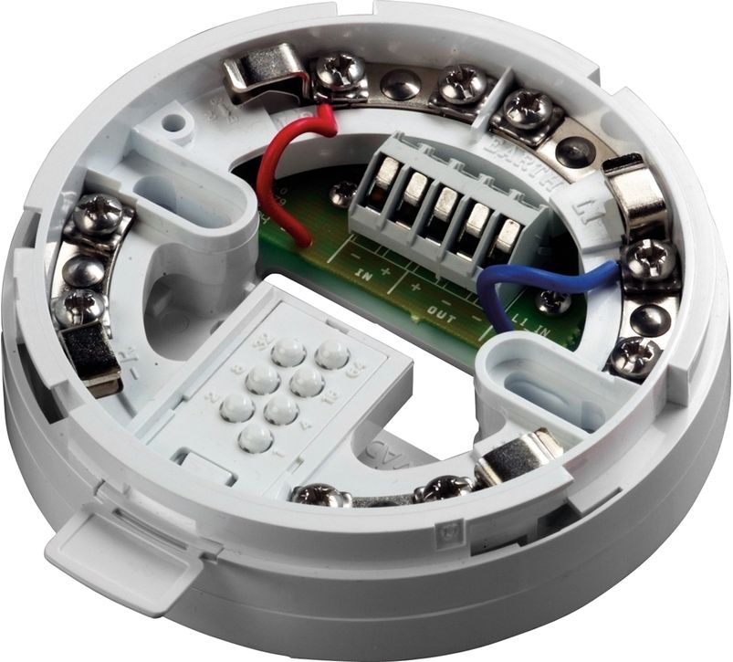
Mechanical ConstructionThe isolating base is a self-extinguishing polycarbonate moulding with nickel-plated steel terminals for connecting a detector. The associated detector can be locked into the base using the normal locking screwBackward CompatibilityThe isolating base is intended for use with equipment using the Apollo XP95 and Discovery communication protocol.The Isolating Base senses and detects short-circuit faults on Discovery loops and spurs.Key FeaturesUp to 20 detectors or their equivalent load, may be installed between isolating bases
High brightness LED
Detects wiring short-circuits
Minimises disruption from short circuits
If a short-circuit or abnormally low impedance occurs, the fall in voltage is sensed and the base isolates the negative supply in the direction of the fault. The isolated section is tested using a current pulse every five seconds. When the short-circuit is removed, the power will automatically be restored.
If it is a requirement that no device is lost in the event of a single short-circuit fault, every detector should be fitted to an isolating base.
In applications where it is not necessary to use an isolating base for each detector, up to twenty detectors or equivalent surge current may be installed between isolating bases. See PIN sheet PP2090 for full information on loop loading between isolating bases.
Consult engineering guides or PIN sheets for quiescent current values of protected devices.
Mechanical ConstructionThe isolating base is a self-extinguishing polycarbonate moulding with nickel-plated steel terminals for connecting a detector. The associated detector can be locked into the base using the normal locking screwBackward CompatibilityThe isolating base is intended for use with equipment using the Apollo XP95 and Discovery communication protocol.The Isolating Base senses and detects short-circuit faults on Discovery loops and spurs.Key FeaturesUp to 20 detectors or their equivalent load, may be installed between isolating bases
High brightness LED
Detects wiring short-circuits
Minimises disruption from short circuits
No reviews found


